This sections shows some photographs of an already mounted IgorPlug USB device. The corresponding circuit board may be found in the Hardware section.
Circuit board
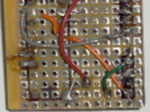
This photo shows the front side of the circuit board. Each component position has been marked using a soft pen. Pin connector for USB cable are found on the lower-left corner. A black point has been drawn in order to show the GND pin (black wire). This should avoid a wrong connection.
The TSOP sensor is connect by the ways of those pins on the lower-right corner. Note that the third pin has been locked. This surely avoids a wrong connection.
The quartz crystal must be pluged into the upper pins. It has been removed for the shake of a better picture.

The following photograph shows most of the soldering points.

In-case mounting
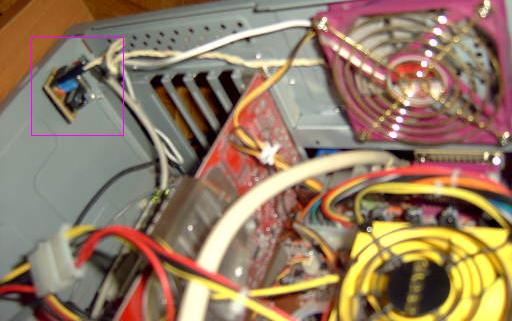
This circuit board is ready to be mounted both externally and internally (in the PC case). The last will give you a confortable aesthetic result.
This photo shows an in-case located board. The TSOP sensor uses a large cable to reach the case's outter space.

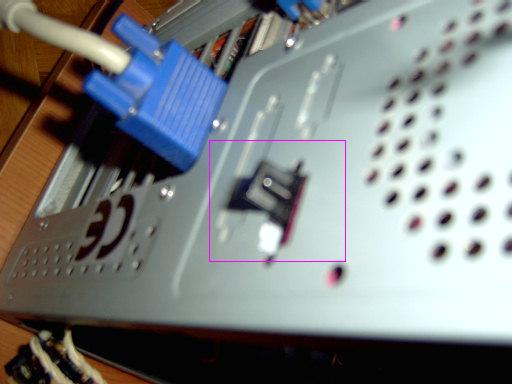
The following one shows the named TSOP sensor outside the case. Note that such sensor is located on the rear part of this PC. This is OK, just because infrared signals will rebound on walls. There is no need for a straight line of sight between the sensor and the remote control. IMPORTANT: Use some material to isolate the back of the circuit board. The computer's case is made of metal, so it may cause some kind of shortcut.

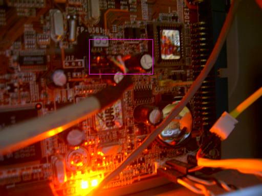
This motherboard has an internal USB port which has been used to plug the device. IMPORTANT: It may be necessary to enable such port in your computer BIOS. Take care not to plug the cable into the motherboard in the wrong way (follow color and pin schema).
