IgorLirc will work only with IgorPlug-USB device, designed by Igor Cesko. Please, visit his homepage in order to obtain complete information about this hardware .
This page is here just to provide help in order to build such a device.
Needed parts
Those electronic parts are easy to find in many stores:
-
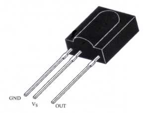
An infrared sensor.
Models TSOP 17xx and SFH506-xx are valid, where
xx stands for the sensor's frequency (Khz).
Any frequency between 36 and 38 Khz will work. For example,
TSOP 1736 works fine.
WARNING: Pin functions are not the same in SFH506-xx model
as in TSOP 17xx model. Look at the corresponding datasheet for
each model.
-
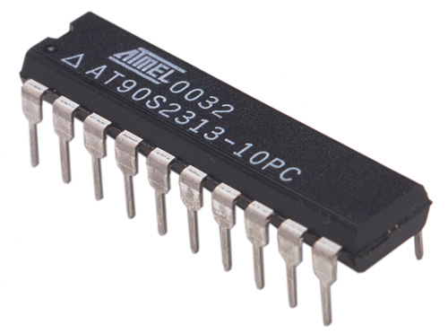
A microcontroller from Atmel.
You may use both AT90S2313 and
AT90S2323 models as you wish.
In this page, we just describe the corresponding
circuit board for AT90S2313 microcontroller.
-
Two sockets (optional) with the same size and pin number as
your microcontroller. It is mandatory whether you don't have a
programmer for the microcontroller's firmware (most probable).
In such case, you must build another (rather simple) circuit for the
programmer, but using the same microcontroller. So, soldering it
to the board is not a good idea.
A socket may be soldered instead. So you can move your microcontroller
in and out of any circuit board.

-
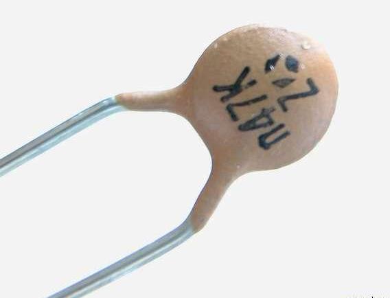
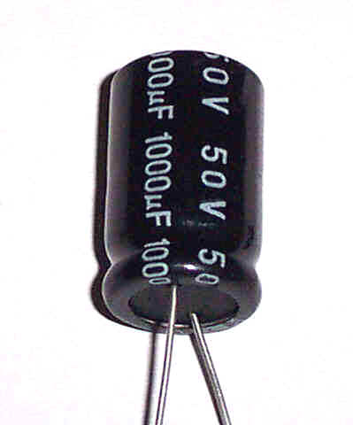
Capacitors. You need one ceramic capacitor and two
electrolitic capacitors. WARNING: take good care of not to
reverse polarity on electrolitic capacitors. They may blow up. No joke.
The shortest pin is the anode.
Capacitances are: 100 nF, 10 microF and 4.7 microF, respectively.
-
A quartz crystal.
12 Mhz in frequency.

-
Resistors. You need four of them
Resistors are
color coded
. Those are the color codes for this circuit:
R1 = Maroon, red, green, gold.
R2 = Maroon, maroon, maroon, gold.
R3 y R4 = Blue, gray, black, gold.

-
Uniprint test board.
In order to build up your circuit.
There are two types: one with small copper points, and another with
horizontal copper tracks. We recommend the first type. Renember:
parts are mounted over the front side, but they are soldered on the
back, where the copper points are found.

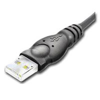
- USB cable. There are two choices. The expensive one is to buy a general purpouse USB cable, then cut one end. The end you should keep is that found in the following photograph. The cheaper option, is to build a custom wire which can be pluged in your PC motherboard. This option allows you to hide the IR device inside yor PC case. You will need some pin connectors for this.
- Pin connectors (optional). It enables some parts to be pluged in and out. Recommended for the quartz crystal, the TSOP sensor and the USB cable. Otherwise, those components must be soldered to the circuit board.
- Some thin copper wire. Just to make some connections.
- USB cable. There are two choices. The expensive one is to buy a general purpouse USB cable, then cut one end. The end you should keep is that found in the following photograph. The cheaper option, is to build a custom wire which can be pluged in your PC motherboard. This option allows you to hide the IR device inside yor PC case. You will need some pin connectors for this.
The price of those components are below 10 euros.
Additionally, you will need a solder and soldering paste. Optionally, a polimeter or multimeter will come in handy, for example, to locate bad connections. A small cutter will be useful, too.
Building up the circuit
The following diagrams show how to place the components and solder them over the test board. The upper one shows the back of the board, where componentes are soldered. The lower one shows the front of the board, where the components are mounted.
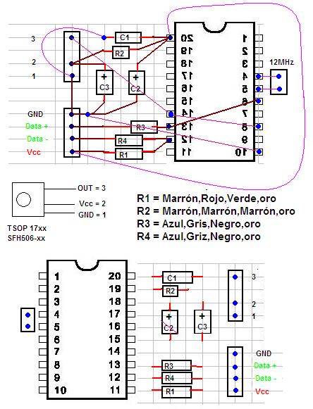
The trick for a handsome circuit is to use the large metal pins of capacitors and resistors as if they were wires. But be sure not to make false contacts with them, since they are not isolated. Metal pins are shown in maroon on the diagram. We need some pieces of wire, too. They are shown in purple.
Pins and connectors
USB cables and connectors have been standarized, including their color coding scheme. Refer to http://www.usbman.com/Guides/BelkinMotherboard_cable_assembly.htm for complete information. This is a summary:
Color coding scheme for USB wires:
Red or Orange = Power, 5 volts (Vcc).
White or yellow = DATA- (D-).
Green or gray = DATA+ (D+).
Blue, black or maroon = Ground (GND).
Motherboard's USB Pins: Each port has two rows of five pins, each row corresponds to one USB device. Pin 1 is located on one corner, and pin 10 on the opposite one. It is usual to find that pin 10 has been removed, so it is easy to figure out which pin is which.
Results
Visit the photo gallery in order to see some mounted circuits.